Model 15A Gauge Valves
APPLICATION-
Pressure Rating: 3000PSI @ -20℉ to 100℉ | 2850PSI @ 300℉ | 2625PSI @ 500℉
INSTALLATION-
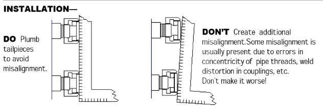
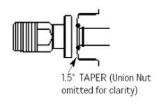
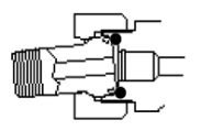
DO Make up unions tight. Use at least an 18″ wrench. Union is designed to crush solid metal along a high ridge, creating a “line” seal between the taper and the flat surfaces.
Union will seal pressure without need for O-ring if alignment is good enough and if the installation torque has been efficiently transmitted into tightening the joint.
However, if there is significant misalignment in the piping arrangement then some of the “umpf” experienced during make-up has been diverted into deflecting the piping. This causes resistance to further turning of the nut and may leave insufficient tightness in the metal to metal seat of the union for sealing. In this case the O-ring will finish the job. The joint needs to be tight enough (close enough) to close the extrusion gap for O-ring to maintain its seal.
More severe MISALIGNMENT can lead to leaks at the union or broken pipe nipples or broken tailpieces. If you are experiencing these difficulties ask for Inferno SPHERICAL UNIONS available as a separate male x male union or built into the valve itself.
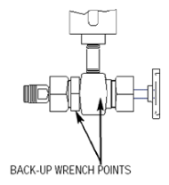
DO Make up unions using a BACK-UP WRENCH on the valve body.
Failure to use back-up wrench causes excessive stress on the connecting nipple and can lead to breakage of nipple or harmful twisting to sight glass.
OPERATION‐
BALL CHECKS…
Open valves full open during operation to assure safety action of ball check in case of glass or gasket failure. Stem must be open more than 1-1/2 turns before ball is allowed to back seat. Extension on end of stem will deny ball a seating position until valve is
opened sufficiently. At this point the extension of the stem retreats enough to allow ball to check closed in event of sudden loss of pressure in the sight glass.
Ball checks are designed to limit flow from vessel in case of accidental glass or gasket failure. They can be of great help in limiting the blow-out effect of pressure acting on a shattered glass But ‐ they are not intended to provide a perfect seal. Dirt, trash and corrosion in the ball check cavity and back seat area will limit the tightness of the emergency shut-off. In such cases there may be some degree of leakage past the ball checks.
Ball check will not activate in case of seepage caused by a leaky gasket. Ball check may not activate at all if cavity is packed with corrosion. Ball check requires pressure in the vessel to activate. About 7″ head of water is sufficient pressure to check the ball in water service with a full flow leak. More pressure is required to check with a choked off leak. Performance in other fluids will vary. Ball check may not activate in extremely viscous fluids.
If in doubt as to whether ball checks are present in an existing installation or whether or not they are working properly you can test as follows: Close off the upper gage valve. Leave the lower valve open. Open a drain valve rapidly and listen for the ball to make an audible “click”. Now repeat process reversing the upper and lower valve position.
Restore fluid level in sight glass by closing drain and then moving both valves into the cracked open position. Cracking the valves open will cause the stem extension to unseat the ball and allow it to drop back into its normal resting place.
If sight glass fails and balls are activated then manually close both valves. Be aware that a small amount of fluid will escape as the balls are dislodged and before stem has a chance to fully close. Take necessary precaution.
BLOW‐DOWN… DON’T blow down sight glass with valves open. High velocity flow will cut seat and lead to failure of valve to close without leakage. This problem is especially common in steam and hot water applications. However if it is not convenient to blow‐down the hot water sight glass with valves in the closed position then DO install a second valve (ball or gate) to insure that a tight shut‐off can be made for maintenance purposes during normal plant operation. A double block system may be required if you experience cutting in the seat area.
Shut off upper and lower valves first, then blow down sight glass through the lower valve’s drain connection, or through an additional outlet at the bottom of the sight glass. Restore fluid level in sight glass by closing vent and drain and then cracking open the upper and lower valves. Cracking the valves open prevents nuisance ball checking. After level has been reestablished open the valves full open. In the full open position the ball is able to check autmatically in case of glass failure. In cracked position it will not check.
SHUTDOWNS… It is usually best to leave valves in normal full open position as the system is de-pressurized. This prevents excessive thermal stress on the sight glass and valves and prevents trapping high pressure fluid. During START‐UP pressure and temperature are allowed to equalize slowly in the sight glass.
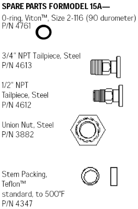
Optional Materials
O-Ring, EPDM E0962-90, Size 2-116, for hot water & steam
P/N 4938
O-Ring, Parofluor Ultra, Size 2-116, for hot water & steam to 525F
P/N 6965
Stem Packing, Grafoil TM, over 500°F
P/N 3509
New Item
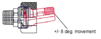
Spherical Union– Corrects for angular misalignment in piping. Reduces all piping strain. Re-usable joint seals gas-tight multiple times.
Best when used with Close Hook-up (CH) level gages having side or back outlets. Position the spherical union between the side or back outlets of the “CH” level gage and the gage valve. If C-C does not match, rotate the vessel connection of the valves until the ball will fit into socket. By allowing the valves to rotate non-parallel to each other the spherical union will correct a relatively large C-C difference between assembly and vessel. Purpose of spherical joint between gage and valve is to eliminate piping strain.
May also be used with CH level gage without valves for direct connection to vessel or piping. Should be used in conjunction with a plain, flat, “Floating Union” in a matched set. In this way angular misalignment and C-C difference may be overcome.
Available in Steel and Stainless, Std. O-Ring is Viton
1/2″x1/2″
3/4″ x3/4″
1/2″ x 3/4″