Installation Instruction: I 93518
Issued: 5/93
Replaces: 2/92
INFERNO
Inferno Manufacturing Corp.
115 Ricou Street
Shreveport Louisiana 71107
318-221-8454
Oblong Rectangular Series
RW-A, TW-A, RW-B, TW-B
WELD PAD INSTALLATION INSTRUCTIONS
2. Use the pad as a template and mark the vessel wall at the top and the bottom of the slot with a pencil.
3. Drill two holes in the vessel wall corresponding to the top and bottom of the slot in the weld pad (Drill two holes for a single section weld pad, four holes for a two-section weld pad, etc.). Use a 1/2″-5/8″ drill.
4. Before welding the weld pad to the vessel, we recommend inserting a steel spacer between the pad and the cover and tightening the bolting to 25-30 ft-Ibs. Do not use a gasket at this point.
Purpose of welding spacer:
* To provide increased rigidity to weld pad during welding, this helps prevent warpage.
* To provide a blockage to the orifices in the welding pad during hydrotest without using the glass. The glass will be installed later, just prior to shipping reservoir base to customer.
The spacer and the cover being tight against the weld pad will also minimize any possible distortion to the gasket seat in the pad due to welding heat. FOR AN EFFECTIVE SEAL AND BEST PERFORMANCE, THE GASKET SEAT MUST REMAIN FLAT AFTER WELDING.
5. Tac-weld the unit in position, then weld all the way around the perimeter of the pad.
6. Give the pad a few minutes to cool, then remove the bolting and the spacer.
7. If desired, a slot in the vessel wall may be made at this time, corresponding to the slot in the weld pad itself. This is an option which may be necessary depending on the application: reflex weld pad or transparent weld pad.
Reflex weld pads are used to read one liquid level only in a 2-phase system (egs. oil/vapor Interface). Transparent weld pads are used to read liquid/liquid interfaces in 3-phase systems (egs. water/hydrocarbon/vapor). In general, when using reflex weld pad, it is not necessary to slot the vessel wall to match the slot in the weld pad; two holes, one to match the top of the slot and one to match the bottom of the slot in the pad are sufficient.
Purpose of drilling holes:
* To allow fluid to pass into the welding pad from the vessel.
If transparent weld pads are to be used, the vessel wall should be slotted.
8. Clean gasket seat in weld pad and cover and make sure there is no welding spatter on the gasket
Purpose of wiping clean:
* To allow glass to sit flat; otherwise breakage may occur.
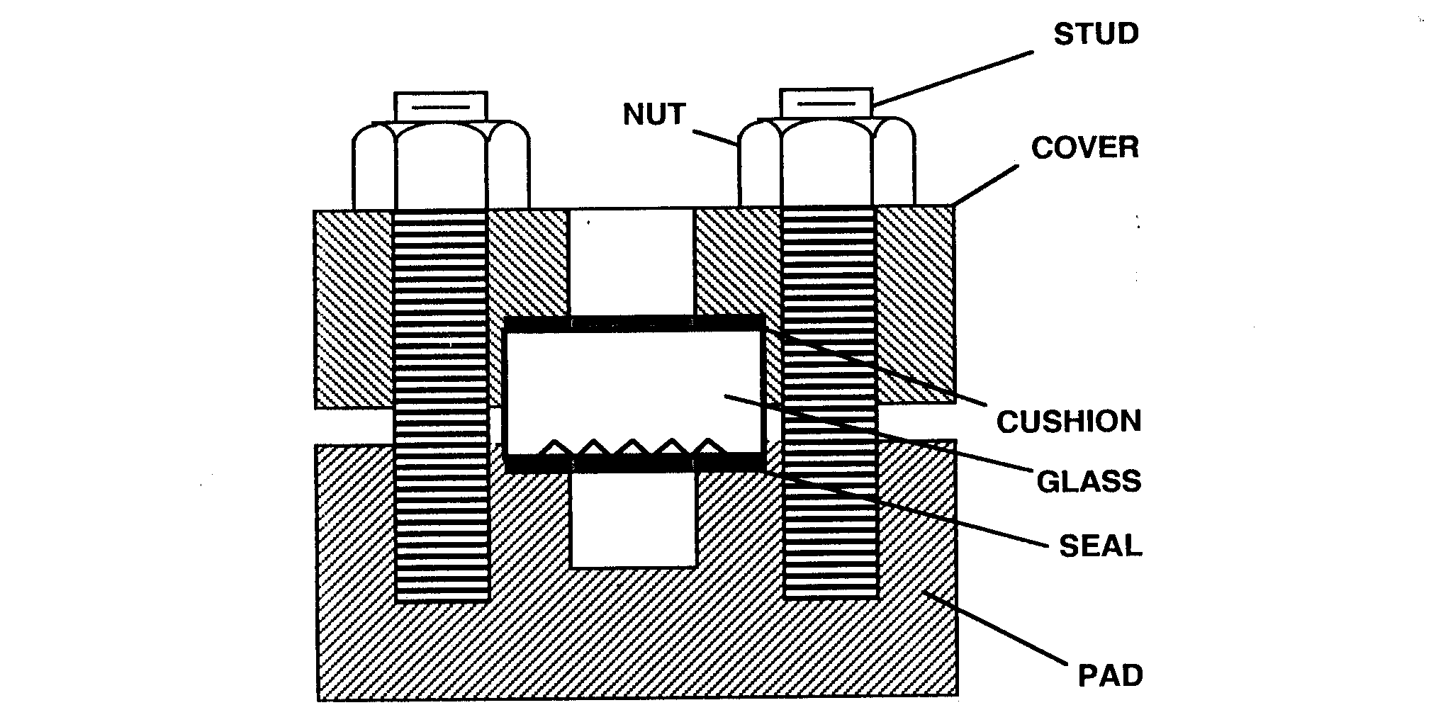
9. Assemble glass and gaskets per “INSTALLATION, OPERATION, AND MAINTENANCE OF INFERNO LIQUID LEVEL FLAT GAGES.”
10. Torque bolting to the following recommended amounts:
RW-A 20 ft-lbs lubricated
TW-A 20 ft-lbs lubricated
RW-B 30 ft-lbs lubricated
TW-B 30 ft-lbs lubricated
SUMMARY
* Mark vessel wall using weld pad as a template.
* Drill holes to match top & bottom of weld pad slot.
* Assemble welding spacer and cover and torque to 25-30 ft-Ibs.
* Weld the pad in desired position.
* Cool down.
* If desired slot the vessel at this time.
Note: Slotting vessel prior to welding on the pad may weaken the vessel and cause the weld pad gasket seat to distort. Therefore we recommend slotting the vessel
* Clean gasket seat of any debris, nicks or burrs.
* Assemble glass and gaskets and torque bolting per “INSTALLATION, OPERATION, AND
MAINTENANCE OF INFERNO LIQUID LEVEL FLAT GAGES.”
NOTE: WELDING SPACERS ARE AVAILABLE FROM INFERNO & SHOULD BE ORDERED WITH THE WELD PAD GAGE ITSELF.

