Inferno Mfg. Corp.
Ref: M101498
4-13-2010
Rev: 2.1
Rev Date: 9-19-12
Inferno TWA series and RWA series
Rectangular style weld pad gages-
Design Information
Rectangular weld gages for seal reservoirs are typically made in the “2 Hole & Channel” design where the weld pad base is not fully slotted but only drilled through at top and bottom. The back of the welding pad is curved to fit the reservoir and a fillet weld is made around the perimeter of the weld pad. The shell of the vessel is drilled with two holes that correspond with the holes in the weld pad. In this design there is no need to cut an elongated opening in the shell.
Other weld pad gages for general purpose are frequently made in the “Full Slot” design to allow the operator to see directly into the vessel. These may be inserted into the vessel wall, which requires a full length opening.
When the vessel is slotted instead of only drilled with two holes the pad is subject to bending forces imposed by the vessel wall as the vessel is hydraulically loaded. These forces act in both the short and long direction of the weld pad. Every vessel behaves differently, depending on shell thickness, diameter and material. Once the glass is installed to the weld pad by means of the retainer flange and bolting it will assume the same shape as the weld pad, even with a relatively soft rubber gasket on top of the weld pad.
A cylindrical shell with a long opening undergoing pressure loading tends to distort in the short direction as hoop forces spread the opening wider in the middle. The cylinder also tends to assume a spherical shape, the long side of the cylinder becomes shorter as the mid span area bulges outward. The extreme condition would resemble a frozen can of soda, somewhat shorter in length than normal and with a larger girth in the mid section.
The ASME Code considers stresses in the shell material as a guide for design; but not deflection amplitudes. A vessel design might pass ASME allowable stress levels in the shell material. However the associated deflection of the shell can be so large that the glass will not be able conform to the changed shape of the vessel without experiencing stresses that exceed its own bending limits which are quite lower than steel. High bending stresses can cause the glass to suddenly break.
It is the vessel designer’s responsbility to make sure that the glass seating surface in the weld pad remains sufficiently stiff as the internal pressure is raised in the vessel. The glass itself should not be subject to bending beyond the limits shown in the table below.
Warpage caused by welding can take the same shape as distortion caused by pressure loading. A straight edge placed on top of the welding pad base and running the long way down the length of the weld pad may reveal a “high” spot at mid span. The problem of distortion caused by welding can be additive in nature to the problem caused by pressure loading because of the similar shape of the deflection.
Flatness of the glass seating area of the welding pad should be monitored after welding and remain within the limits shown below to minimize the chance of glass breakage during installation (bolt tightening, hydrotest) or later in service.
The glass seating area should be flat within the following amounts. These limits are calculated according to the bending strength of the glass and further limited by the glass manufacturer’s maximum out of flatness recommendations :
|
Glass Size
|
Typical Model No.
|
Max. Allowable Out-of- Flatness
|
|
1
|
RWA-11, TWA-11
|
.001″
|
|
2
|
RWA-12, TWA-12
|
.002″
|
|
3
|
RWA-13, TWA-13
|
.003″
|
|
4
|
RWA-14, TWA-14
|
.004″
|
|
5
|
RWA-15, TWA-15
|
.005″
|
|
6
|
RWA-16, TWA-16
|
.005″
|
|
7
|
RWA-17, TWA-17
|
.005″
|
|
8
|
RWA-18, TWA-18
|
.005″
|
|
9
|
RWA-19, TWA-19
|
.005″
|
Pressure ratings are not stamped on the RWA and TWA series weld pad gages because the weld pad gage manufacturer cannot control the degree of flatness both after welding and in the hydraulically loaded condition as the vessel is pressurized. A table of ratings is published showing the pressure capacity of the weld pad assembly assuming that the flatness limits shown above are maintained in the final welded and pressure loaded condition.
Suggestions to Reduce Distortion from Welding Attachment of Weld Pad Gages
1- Provide good fit-up.
2- Use smallest size weld permitted by Code rules.
3- Use as few passes as practical.
4- Use as low heat input as practical.
5- Use full penetration groove welds, double vee, instead of fillet welds.
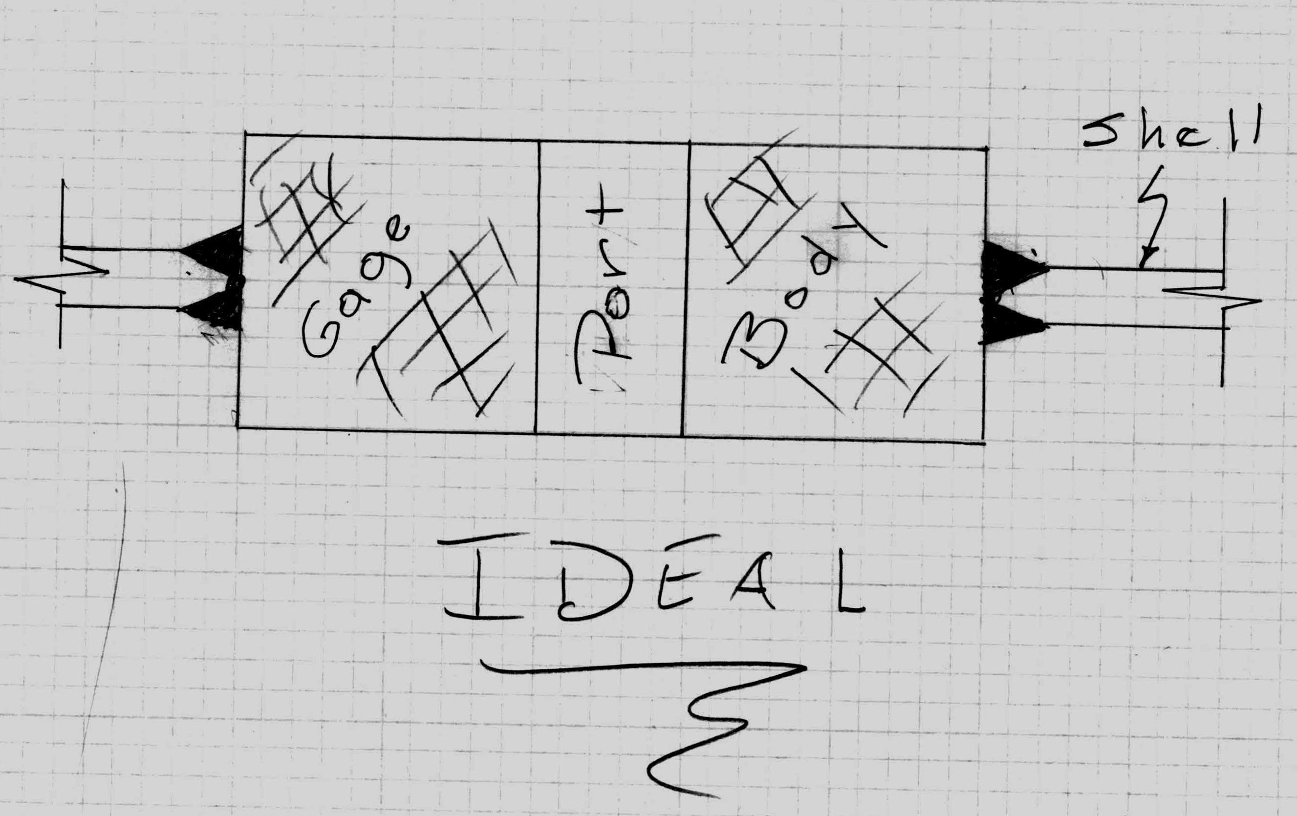
6- Place the welds near the neutral axis of the gage body. See sketch.

7- Balance welds about the neutral axis.
8- Weld opposing surfaces alternately immediately following each other.
9- Use intermittent back-step welding.
10- Use clamps, jigs, fixtures or stiff-backs as needed to maintain alignment.
11- Preheat as is practical.
More information on controlling weld distortion can be found in the following articles available on the web, written by Mr. Omer Blodgett, Senior Design Consultant with the Lincoln Electric Company and published in Welding Magazine / Welding Design & Fabrication
http://weldingdesign.com/blodgett/wdf_68978/
