Horizontal Layout with Flexbox

Gage Selector

Step 1. Combo or Gage Only

Image 1
Image 2
alternative_text alternative_text

Step 2. Fill one box only - "Enter"

Step 2. Fill one box only - "Enter"

for Close Hookup Gages, enter Gage Port C-C, if known


USER HAS SELECTED THE OVERRIDE OPTION
Error: Value must be at least 3.75
Error: Value must be at under 159

Step 3. Four Options - Scroll Down

alternative_text alternative_text

Single Union

End Connected Level Gage

OPTIONAL Override (End Connected)

This form defaults to the longest LG that will fit within your specified vessel centers. You can select an optional shorter LG in the dropdown below.


USER HAS SELECTED THE OVERRIDE OPTION

Step 3. Click on a blue Gage Model link to create a datasheet

#
Gage Model
PSI @ 100°F **
1
2
3
Visible (in)
Min. Vessel C-C (in) ****
LG OAL (in)
Combined Pipe Nipple
Overall Length (in)
Visible (in)
LG OAL (in)
Min. Vessel CC Single Union Valves ****
Min. Vessel CC Double Union Valves ****

** Deratings apply for B7M and B8M bolting and TFE gaskets. Pressure rating limited to 250 WSP for boiler service and 450 WSP for non-boiler steam. Contact factory for boiler service (ASME B&PVC Section I).

*** Minimum recommended combined nipple length = 3" (1-1/2" + 1-1/2"), depends on vessel CC

**** If using Inferno 90° angle gage valves, use these vessel cc dimensions for design purposes.

Warning, 1 - Insulation jackets require 3" minimum upper and lower connecting pipe nipple length (6" total)

Warning, 2 - To avoid interferience with valve handwheel, LG with non-frost extension kit - assembled per orientation FIG 4-1 - requires 2.25" minimum upper and lower connecting pipe nipple length (4.5" total)

Warning, 3 - No-weld bracket kit requires 3.75" minimum length of lower connecting pipe nipple

Warning, 1 - Insulation jackets require 3" minimum upper and lower connecting pipe nipple length (6" total)

Warning, 2 - To avoid interferience with valve handwheel, LG with non-frost extension kit - assembled per orientation FIG 4-1 - requires 2.25" minimum upper and lower connecting pipe nipple length (4.5" total)

Warning, 3a - No-weld bracket kit requires 3.75" minimum length of lower connecting pipe nipple (Single Union)

Warning, 3b - No-weld bracket kit requires 2.25" minimum length of lower connecting pipe nipple (Double Union)

alternative_text alternative_text

Double Union

OPTIONAL Override (End Connected)

This form defaults to the longest LG that will fit within your specified vessel centers. You can select an optional shorter LG in the dropdown below.


USER HAS SELECTED THE OVERRIDE OPTION

Step 3. Click on a blue Gage Model link to create a datasheet

#
Gage Model
PSI @ 100°F **
4
5
6
Visible (in)
Min. Vessel C-C (in) ****
LG OAL (in)
Combined Pipe Nipple
Overall Length (in)

** Deratings apply for B7M and B8M bolting and TFE gaskets. Pressure rating limited to 250 WSP for boiler service and 450 WSP for non-boiler steam. Contact factory for boiler service (ASME B&PVC Section I).

*** Minimum recommended combined nipple length = 3" (1-1/2" + 1-1/2"), depends on vessel CC

Warning, 1 - Insulation jackets require 3" minimum upper and lower connecting pipe nipple length (6" total)

Warning, 2 - No-weld bracket kit requires 2.25" minimum length of lower connecting pipe nipple

alternative_text alternative_text

OPTIONAL Override (Close Hookup)

This form defaults to the longest LG that will fit within your specified vessel centers. You can select an optional shorter LG in the dropdown below.

USER HAS SELECTED THE OVERRIDE OPTION

Side Connected Close Hookup

SIDE CONNECTED CLOSE HOOKUP

Step 3. Click on a blue Gage Model link to create a datasheet

#
Gage Model
Visible (in)
Vessel Connection
Side Ports On Gage Chamber
Gage Port C-C (in)
Vessel C-C (in)
Min. Gage Port C-C (in)
Min. Vessel C-C (in) ****
PSI @ 100°F **
7
8
9
10
11
12

* Additional options available such as ½” M-NPT, 1” M-NPT with Adapter, ANSI Flanged etc. Click a blue Gage Model to further define your requirements and create a data sheet specification.

** Deratings apply for B7M and B8M bolting and TFE gaskets. Pressure rating limited to 250 WSP for boiler service and 450 WSP for non-boiler steam. Contact factory for boiler service (ASME B&PVC Section I).

**** Based on Inferno model FT15, FT25 & 15A offset pattern gage valves, arranged "offsets inside" (three-quarter inch (3/4") offset per valve, 1-1/2" total offset)

alternative_text alternative_text

OPTIONAL Override (Close Hookup)

This form defaults to the longest LG that will fit within your specified vessel centers. You can select an optional shorter LG in the dropdown below.

USER HAS SELECTED THE OVERRIDE OPTION

Back Connected Close Hookup

BACK CONNECTED CLOSE HOOKUP

Step 3. Click on a blue Gage Model link to create a datasheet

#
Gage Model
Visible (in)
Vessel Connection
Back Ports On Gage Chamber
Gage Port C-C (in)
Vessel C-C (in)
Min. Gage Port C-C (in)
Min. Vessel C-C (in) ****
PSI @ 100°F **
13
14
15
16
17
18

* Additional options available such as ½” M-NPT, 1” M-NPT with Adapter, ANSI Flanged etc. Click a blue Gage Model to further define your requirements and create a data sheet specification.

** Deratings apply for B7M and B8M bolting and TFE gaskets. Pressure rating limited to 250 WSP for boiler service and 450 WSP for non-boiler steam. Contact factory for boiler service (ASME B&PVC Section I).

**** Based on Inferno model FT15, FT25 & 15A offset pattern gage valves, arranged "offsets inside" (three-quarter inch (3/4") offset per valve, 1-1/2" total offset)
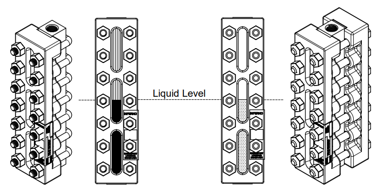
Combined Image

Reflex

Prismatic glass

2-phase system

Liquid - Vapor

  • water - gas
  • oil - gas
  • water - steam (250 WSP)
  • high contrast, visible from distance
  • less weight
  • less expensive

Transparent (See-Thru)

Plain glass

3-phase system

Liquid - Liquid aka "Interface"

  • water - oil - gas
  • water - steam (450 WSP w. Mica Shields)